Best Electric Bikes for Seniors UK 2026: Lightweight Step-Through Models
Best Electric Bikes for Seniors UK 2026: Lightweight Step-Through Models Buyer’s Guides • Senior Riders • Step-Through E-Bikes Best Electric Bikes for Seniors UK 2026:
DIY Guides • Conversion Kits • Bafang BBSHD
Published: June 22, 2026 • Reading time: ~20 min • All4eBikes, Cardiff
The BBSHD sits above the BBS02B in Bafang’s mid-drive range. It is larger, heavier, and requires a wider bottom bracket shell — but delivers substantially more torque and handles sustained high-load conditions the BBS02B struggles with. Before committing to a BBSHD build, confirm it is the right tool for your application.
| Specification | BBS01B | BBS02B | BBSHD |
|---|---|---|---|
| Nominal power | 250W | 750W | 1,000W |
| Peak torque | ~80 Nm | ~120 Nm | ~160 Nm |
| BB shell required | 68mm / 73mm BSA | 68mm / 73mm BSA | 100mm / 120mm BSA |
| Motor weight | ~2.45 kg | ~2.9 kg | ~3.9 kg |
| Controller current (stock) | 15A | 25A | 30A |
| UK road legal? | ✓ Yes (250W version) | ✓ When programmed | ✓ When programmed |
| Best for | Road commuter | All-rounder, hilly commutes | Fat bike, cargo, e-MTB, high-load off-road |
The BBSHD makes most sense for: fat bikes and plus-tyre builds (100mm BB is common on these), cargo bikes and heavy-load riders, high-power off-road e-MTB builds, and any application where the BBS02B has proven thermally limited on long sustained climbs. If your frame has a standard 68mm BB and you want a road-legal commuter, the BBS02B is almost certainly the better fit.
Frame compatibility is the single most common point of failure in a BBSHD build. Measure before you order — not after.
The BBSHD motor sleeve has an external diameter of 33.4mm and requires a BB shell with a 33.6mm internal bore (standard BSA/English thread). The motor comes in two widths:
To measure your BB shell: remove the existing bottom bracket, clean the shell, and measure the internal width between the left and right faces with a vernier calliper. If in doubt, bring your frame to the workshop and we will measure it for you at no charge.
The BBSHD has a larger secondary reduction gear housing than the BBS02B, which protrudes further on the chain side. On some frames — particularly those with aggressive chainstay shapes — this housing will contact the chainstay and prevent the motor seating correctly.
The test: dry-fit the motor in the BB shell without tightening the lock ring. Check the gap between the secondary gear housing and the nearest chainstay face. You need a minimum of 2–3mm clearance on all sides. If there is contact, the build needs further assessment before proceeding.
The BBSHD requires a BSA (English/ISO) threaded shell — right side right-hand thread, left side left-hand thread. It is not compatible with Italian threaded shells, PF30, BB86, BB92, or BB386 press-fit shells without adaptors. Press-fit adaptors for the BBSHD’s wider body are not reliable — we do not recommend them.
Use a crank puller matched to your crank type. Loosen the crank bolt first (usually 8mm hex), thread the puller body into the crank, then advance the centre spindle until the crank pops free. Do both sides. If you have Shimano Hollowtech or similar bonded cranks, use the appropriate splined tool.
Identify your BB type and use the correct splined or pin-type removal tool. On a BSA shell: the right-side cup is left-hand thread (loosens clockwise); the left-side cup is right-hand thread (loosens anticlockwise). Apply penetrating oil and wait 20 minutes if the BB has been in place for years. Seized BBs are extremely common on bikes that have seen wet UK winters — do not force it without penetrating oil.
Wire-brush or clean all thread surfaces. Remove old grease, grit, and any thread-locking compound residue. Inspect carefully for damaged or stripped threads — the motor’s M33 lock rings need clean threads to torque properly. Damaged threads should be re-chased with a tap by a bike shop before proceeding. A stripped BB shell is not a minor issue — it requires frame repair or replacement.
On most production frames the two shell faces are parallel and smooth. On older or budget frames they can be slightly uneven, causing the motor to sit at an angle. If the dry-fitted motor rocks or won’t sit flush, have the shell faced at a bike shop before continuing. A faced shell costs far less than diagnosing a noisy motor later.
Apply a thin, even coat of anti-seize compound to the internal shell threads. This prevents galvanic corrosion between the shell and the lock rings, and ensures the motor can be removed in future without damaging the shell. Do not use thread-locking compound inside the shell — the lock rings must remain removable for maintenance.
Hold the motor with the output shaft pointing toward the right (chain side) of the frame. Lower the motor sleeve into the BB shell from the right. The sleeve OD is 33.4mm and the shell ID is 33.6mm — it should slide in with light resistance. Do not force it. If it binds, remove and check for thread burrs. Before seating fully, rotate the motor in the shell to plan the harness connector port position — ideally pointing upward or slightly forward for clean cable routing.
Slide the metal retaining bracket onto the left side of the motor sleeve, with the radial ridges facing the BB shell edge. Thread the two M6 bolts finger-tight only at this stage — final tighten comes after the lock rings are torqued. The bracket stops the motor rotating in the shell under load.
The inner grey steel lock ring has 4 notches and threads onto the motor sleeve from the left, clockwise. Thread it finger-tight. Then fit the M33 4-notch socket and torque wrench and tighten to 50 Nm. This is the single most critical fastener on the entire installation. Under-tightening causes the motor to work loose and strip the BB shell threads — a failure that can write off the frame.
The outer black aluminium lock ring threads on outside the inner ring. Use the 16-notch socket. Torque to 25 Nm — lower than the inner because it is aluminium and will strip if over-tightened.
With both lock rings torqued, final-tighten the retaining bracket bolts to 10 Nm. Hold the bracket pressed upward against the shell edge while tightening — the radial ridges need to bite into the shell to resist motor rotation effectively.
With the motor secured, physically check the gap between the secondary reduction gear housing and the chainstay on the chain side. Run your fingers all the way around the housing. There must be clear daylight on all sides. Any contact needs addressing before wiring begins.
The BBSHD uses a proprietary spider with a 104mm BCD bolt pattern. The included chainring is typically 44T or 46T. For off-road builds with wide-range cassettes, many builders drop to 42T or 38T for better mechanical advantage on climbs. Avoid 52T or larger — at BBSHD power levels these stress the chain aggressively. Steel chainrings outlast aluminium by a significant margin under motor load — fit a steel option if you are building for serious mileage.
Mount the chainring on the spider with Loctite 243 on the bolt threads. Torque chainring bolts to 6–8 Nm. Before fitting the cranks, check chainline: the chainring centre should align within 2mm of the centre of the cassette’s middle sprocket. On a BBSHD in a 100mm shell, the chainline typically sits 52–56mm from the frame centreline. Adjust using an outboard spacer behind the chainring if needed.
Slide each crank arm fully onto the splined output shaft. Insert the crank bolt and tighten to 12–15 Nm with a 6mm hex key. The cranks are aluminium — do not force or cross-thread.
Thread the chain through the derailleur (if fitted) and onto the chainring. Size for length: on the largest rear sprocket and chainring combination, with no derailleur wrap, the chain should have approximately 2 links of slack. Add a quick-link and close. Spin the cranks by hand and confirm smooth running through all gears.
The BBSHD main wiring harness connects the motor to the display, throttle, brake sensors, PAS sensor, speed sensor, and battery. Take time to route cables cleanly before plugging anything in.
Hold the harness along its intended route and confirm it reaches all connection points without pulling tight or creating sharp bends. The main harness exits the motor at the connector port — route upward along the down tube toward the bars. Use cable ties at 20–30cm intervals. Never route cables near the chain path.
The display connector is a keyed waterproof circular plug. Match the guide pin and push until it clicks. On Bafang UART systems this is the green 5-pin connector; CANbus systems use a different connector. Do not force — keyed connectors only seat in one orientation.
Brake sensors clip onto or replace your existing brake levers, connecting via a 2-pin JST connector. When the lever is squeezed, motor power cuts immediately. Route sensor cables along brake housing and tie neatly. Do not omit brake sensors — they are a safety system, not optional.
The throttle connects via a 3-pin JST connector. Mount it in a position reachable without moving your hand off the grip. On a UK road-legal build the throttle is typically enabled for walk assist only (up to 6 km/h). For off-road builds it can be configured for full-power throttle use via the programming cable.
Once all connectors are plugged in, cable-tie the harness at every natural anchor point. Tuck excess cable into a loop. Keep the battery connector end accessible. Do not cut harness cables to length unless you are confident re-crimping the connectors.
Slide the PAS (Pedal Assist Sensor) magnetic disc onto the left side of the motor housing as indicated. Secure the retaining screw with a T20 Torx security bit to 1.5–2 Nm. The disc must be concentric with the motor shaft and spin freely.
The PAS sensor body mounts on the motor housing and reads the disc magnets as the cranks rotate. The gap between sensor face and disc must be 1–3mm. Too large and pedal assist response will be sluggish or non-existent. Too small and the disc will contact the sensor. Use a feeler gauge to verify, then tighten the sensor mount.
Clip the speed sensor magnet to any rear wheel spoke. Mount the sensor body on the chainstay so the magnet passes within 3–5mm of the sensor face during wheel rotation. If the gap exceeds 5mm, use the included spacers to bring the sensor closer. Tighten the mounting bolt to 1.5–2 Nm.
Run both sensor cables up the chainstay and seat tube, securing with cable ties. The speed sensor and PAS connectors are keyed differently and will not cross-connect.
The display clamps to the handlebar via a two-piece aluminium collar. Position for easy visibility. Tighten the collar bolt to 1 Nm — just enough to hold position. Do not overtighten; the collar threads are fine and strip easily.
Mount the control pad (up/down/power) where your thumb reaches the buttons naturally without moving your grip. Tighten its M3 clamp screw to 1 Nm. Route the cable to the display and connect.
The BBSHD runs on 48V or 52V. Do not connect a 36V battery — the controller minimum voltage is higher than 36V systems and the BMS protection voltages will not align correctly. For a road-legal build with a 25 km/h speed limiter, a 48V pack is perfectly adequate. For an off-road or unrestricted build, 52V gives noticeably better top-end performance and a flatter discharge curve. Minimum recommended capacity: 17.5Ah (840Wh+). Browse our battery range — all packs are spec’d to handle Bafang mid-drive current demands.
Use a workstand or turn the bike upside down before first power-on. If the PAS sensor or throttle triggers unexpectedly, a freely-spinning rear wheel is far safer than a bike leaning against a wall.
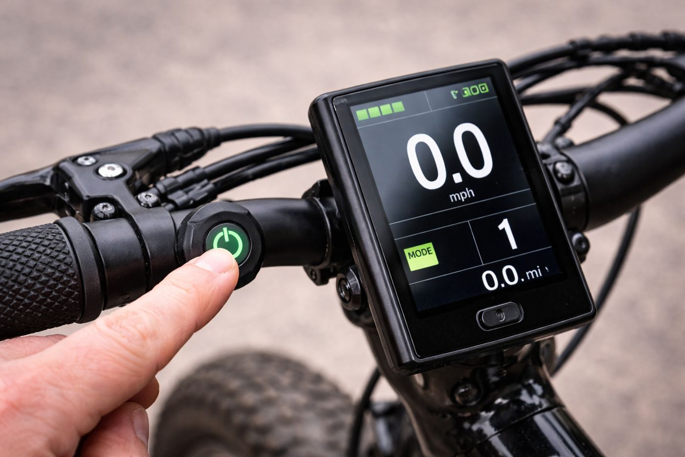
Plug the battery connector. Turn on the battery’s power switch if it has one. Hold the display power button for 2–3 seconds until the display activates. You should see voltage or battery level, assist level (usually 1), and wheel speed (0 at standstill). If the display does not light up, check the battery is charged and the main connector is fully seated.
With the rear wheel in the air, pedal slowly by hand. The motor should engage within 1–2 crank rotations and spin the wheel. Release the pedals — the motor should stop within another half-rotation. Test each PAS level. If the motor does not engage, check the PAS sensor gap. If it does not stop promptly, check the disc is concentric.
With the motor running in PAS mode, squeeze each brake lever. Power must cut immediately. If power does not cut, check the brake sensor connection. Do not ride the bike until brake cut-offs are confirmed working on both levers.
The BBSHD ships from the factory with settings that are not UK road-legal and are also not optimised for most builds. Programming the controller is mandatory for public road use, and significantly improves pedal assist feel and battery efficiency regardless of legality.
You need a Bafang USB programming cable (available from our parts section) and a Windows PC running the Bafang Config Tool. The cable connects in place of the display connector while the battery is live.
| Parameter | Factory default | UK road-legal setting |
|---|---|---|
| Speed limit | 35+ km/h | 25 km/h (15.5 mph) |
| Wheel diameter | 26” | Set to your actual wheel size |
| Low battery cutoff | 41V | 44V (48V battery) / 46V (52V battery) |
| PAS start current | High (abrupt) | Lower value for smoother assist onset |
| PAS stop delay | 250ms | 250ms (leave unchanged) |
| Speed sensor signals | 1 | Match to your magnet count (usually 1) |
We’re Cardiff’s dedicated eBike conversion workshop, based in Roath (CF24). We handle the full BBSHD installation — motor, battery, display, cable routing, chainline, and full EAPC programming — with a road test before handover. Carbon frames, non-standard BB shells, and complex builds welcome.
Visit us: 2 Beresford Road Lane, Cardiff, CF24 1QU
Hours: Mon–Fri 11am–6pm • Sat 11am–3pm • Sun closed
Got a question about your specific frame or build? Message us on WhatsApp with your frame details and we’ll give you a straight answer before you order anything.
Best Electric Bikes for Seniors UK 2026: Lightweight Step-Through Models Buyer’s Guides • Senior Riders • Step-Through E-Bikes Best Electric Bikes for Seniors UK 2026:
E-Bike Battery Fully Charged But Not Working? Troubleshooting Guide Troubleshooting • Batteries • E-Bike Guides E-Bike Battery Fully Charged But Not Working? Complete Troubleshooting Guide

Your ebike professionals!
2 Beresford Road Lane
Cardiff
UK
CF24 1QU
Welcome to ALL4EBIKES!
Typically replies within minutes
WhatsApp Us
🟢 Online | Privacy policy
WhatsApp us